Drive a WS2812B strip with an UART
The WS2812B is the powerhorse of modern RGB leds. The protocol to drive them is very simple, but not to easy to implement as it involves precise timings. Since another protocol that involves precise timings is UART, it makes sense to try to combine them.
Research
Driving a WS2812B is all about very precise timings.
| Symbol | Parameter | Min | Typical | Max | Units |
|---|---|---|---|---|---|
| T0H | 0 code ,high voltage time | 200 | 350 | 500 | ns |
| T1H | 1 code ,high voltage time | 550 | 700 | 850 | ns |
| T0L | 0 code , low voltage time | 650 | 800 | 950 | ns |
| T1L | 1 code ,low voltage time | 450 | 600 | 750 | ns |
| RES | low voltage time | 50 | µs |
This, according to Adafruit, always requires a real-time MCU to drive correctly.
The control signal has very strict timing requirements, and some development boards (such as Netduino or Raspberry Pi) can’t reliably achieve this in every situation.
An UART is such an MCU, albeit very specialized, therefore it makes sense to try to reuse it.
That isn’t a very novel idea and there’s some information around that does exactly that. The closest example I could find was Josh’s articles about using the Raspberry PI miniUART and its explanation. The main issue with that article is that
- it is limited to 1 WS2812
- it leverages some very specifics of the Raspberry Pi
Nonetheless, it does give somes hints on how to extend it further :
- The UART TTL protocol is active low, whereas the WS2812 protocol is active high.
- Each bit of the WS2812 protocol can be emulated by 3 bits of UART, either
100or110to emulate a0or1respectively - Only the emulation of the
0of the WS2812 protocol is really time sensitive, as its 1st high bit has a limited time unless being considered as a1. - Bits have to be send without big pauses, otherwise it is seens as a RESET
Implementation
Theory
Inverting the active low to active high is pretty simple: just use an RTL inverter made with 2 resistors and a NPN.

Simple RTL Inverter (source: Wikipedia)
The only very narrow time constraints is that the 0 bit has to be high for at most 500ns. Which means a least a 2.5Mb baud rate for the UART. This is very fast, as the ubiquitous CH340 only goes up to 2Mb according to the datasheet.
The inverted UART TTL protocol starts with a 1 as the start bit, which is perfect as so does the WS2812 protocol. Which means the 8 bits can be encoded as START + 2 bits, then 2 * 3 bits.
A single byte with 8N1 encoding can perfectly encode 3 bits of the WS2812 protocol.
I won’t go into the details of it, as the explanation from Josh is already pretty straighforward.
Practice
Slow inverter
A naive RTL inverter wasn’t fast enough. Basically it is because when the NPN is in saturation, it needs a lot of current out of the base to go back to cutoff. I needed to have a much faster cutoff.
Acquisition with 2/8 channels at 12 MHz
in: """"""""""""\..................................................
out:............................................................/""
Output of sigrok-cli -O ascii. Each char is a sample at 12MHz, so around 83ns
It is a regular RTL inverter, so placing a capacitor in parallel with the input resistor decreases the time needed for a driving stage to forward-bias a driven stage’s base-emitter junction. I was hinted to use a 1N4148-based Baker clamp which is designed for that exact purpose as it doesn’t allow the NPN into saturation. It did work, but only achieved a 4x increase. I also tried with just a schottky diode (1N5711), to end up with a so-called schottky transistor, with similar increases.
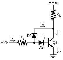
Baker Clamp Inverter (source: Wikipedia)
Then after several experiments, I replaced D1 with a red LED and D2 with a green LED and the cutoff was almost instant.
Acquisition with 2/8 channels at 12 MHz
in: """"""""""""\...../"""""""""""\.........../"""""\.........../"
out:............../"""""\.........../"""""""""""\...../"""""""""""
Here it is much better!
Avoid a slow sending to USB
As the host is not a real time OS, the sending to the UART needs to be done as fast as possible. If the process that sends the data is stalled, the 50µs timeout will be quickly reached.
A way to do that is to prepare the whole data upfront, buffer it, and send it in a single batch. The buffer can be done internally of the converter, or externally.
#include <stdlib.h>
#include <unistd.h>

#define BUFFER_SIZE 64 * 1024 // 64kiB

int main() {
      ssize_t bytes_read;

      char* buffer = malloc(BUFFER_SIZE);
      if(!buffer) {
            exit(EXIT_FAILURE);
      }

      // Read from standard input to local buffer
      ssize_t buffer_len = 0;
      while ((bytes_read = read(STDIN_FILENO, buffer + buffer_len, BUFFER_SIZE)) > 0) {
        buffer_len += bytes_read;
        buffer = realloc(buffer, buffer_len + BUFFER_SIZE);
      }

      // Write the local buffer
      ssize_t bytes_written;
      char* out_buffer = buffer;
      while ((bytes_written = write(STDOUT_FILENO, buffer, buffer_len)) > 0) {
        out_buffer += bytes_written;
        buffer_len -= bytes_written;
      }

      return 0;
}
flushatonce.c
Its usage is very straightforward :
... | flushatonce > /dev/ttyUSB0
Converter : ws2812bify
I created ws2812bify to convert an extended NUA format to an UART-ready stream.
Again the usage is very simple, just remember to setup the baudrate to 2.5Mb.
stty -D /dev/ttyUSB0 2500000
./ws2812bify < file.nua > /dev/ttyUSB0
The NUA format
Origin
The NUA format was invented by Josh Levine in his NeoUart project.
It is a textual format that has 1 event per line. The event/line has the following format:
[DD]RRGGBB where [DD] is an optional duration in 1/100s of seconds, and
and RR, GG, and BB are the brightness levels for red, green, and blue
respecively.
All values are hex numbers in the range 00-ff. The case is not relevant.
Examples of pixelspecs:
- 000000=Black
- 05FFFFFF=white for .05s
- 80000080=50% blue for 1.28s
It is used to drive a single neopixel RGB led.
Extension
In order to be able to write whole strips, I need to extend the protocol a little.
Each line still represents an event, but it can be of unlimited length.
It is enough to simply add a space than another RRGGBB hex numbers. A line represents a single “transaction”, that is send to the line without any RESET in between.
RESETS are sent at the end of each line. The duration is what is waited before emitting the next line. Note that it is an “at least” duration. Due to the non-realtime nature of the host OS, delays can eventually be longer.
[DD]RRGGBB[ RRGGBB[ RRGGBB] ... ]
[DD]RRGGBB[ RRGGBB[ RRGGBB] ... ]
[DD]RRGGBB[ RRGGBB[ RRGGBB] ... ]
[DD]RRGGBB[ RRGGBB[ RRGGBB] ... ]
So a typical file for a 8 neopixels rain fall is
05000000 000000 000000 000000 000000 000000 000000 000000
05FFFFFF 000000 000000 000000 000000 000000 000000 000000
05000000 FFFFFF 000000 000000 000000 000000 000000 000000
05000000 000000 FFFFFF 000000 000000 000000 000000 000000
05000000 000000 000000 FFFFFF 000000 000000 000000 000000
05000000 000000 000000 000000 FFFFFF 000000 000000 000000
05000000 000000 000000 000000 000000 FFFFFF 000000 000000
05000000 000000 000000 000000 000000 000000 FFFFFF 000000
05000000 000000 000000 000000 000000 000000 000000 FFFFFF
05000000 000000 000000 000000 000000 000000 000000 000000
Which leads to this video.